
Sound reactive room lighting using Arduino and LED strips
In a recent journal entry I said I would post more details on the lights I’m using in my apartment. I wanted to spend some more time on the program itself first, but the weekend disappeared too quickly, so that will be an ongoing process. For now, here are some parts lists and information on setting up. I’ll also try to make a similar post for my rainbow spirit hood.
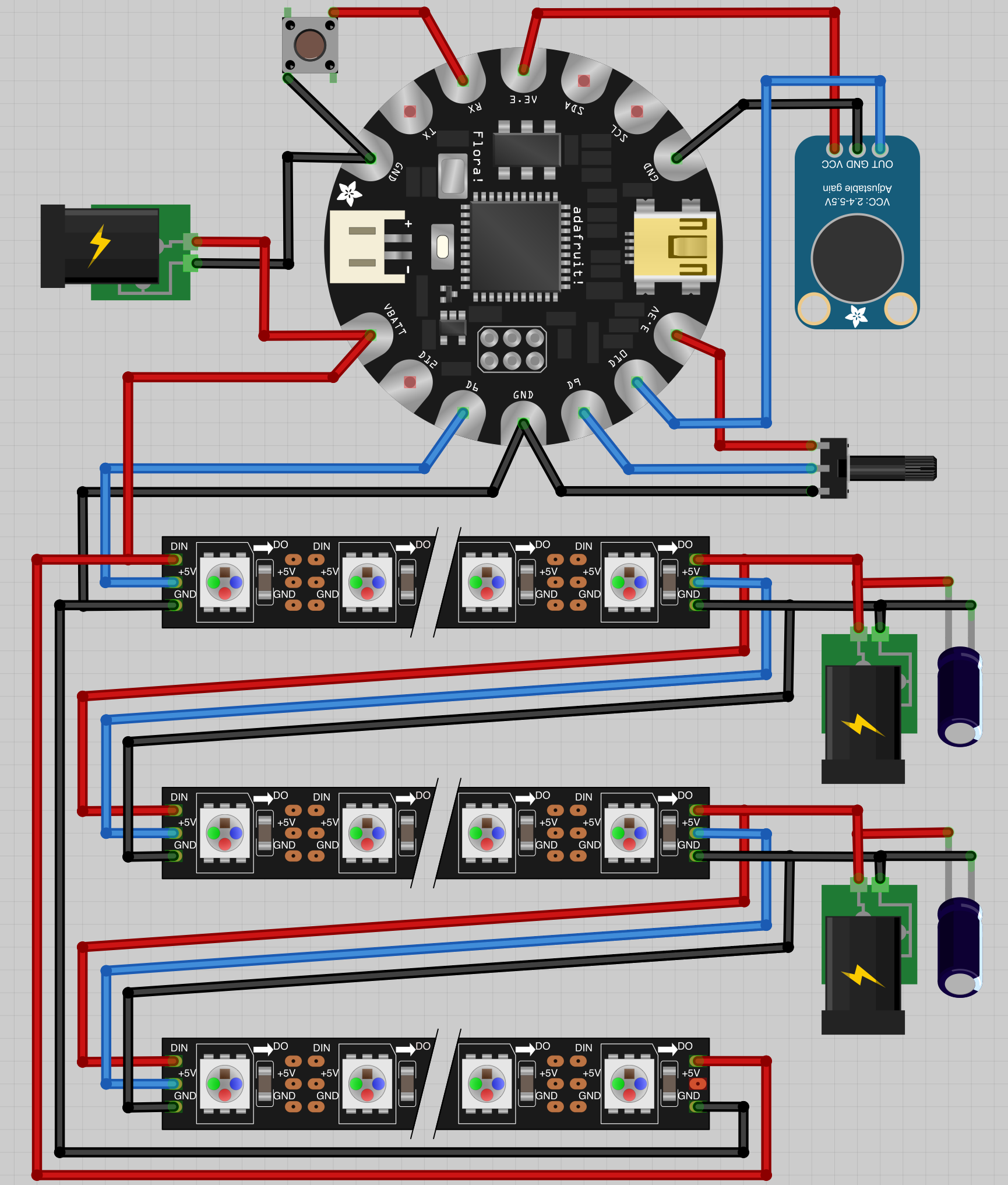
Room lights diagram. Note the NeoPixels image has the data and +5V switched. The data is actually between the ground and voltage." class="mt-image-none" height="2033
I’ve lined the walls with 12 meters of individually addressable RGB LED strip lighting and control it with an Arduino that has a microphone, switch and potentiometer attached. I’m using three 10 amp 5 volt power supplies. All the credit for my understanding of wiring all this stuff goes to Adafruit’s NeoPixel Überguide, and the basic process of volume averaging by which my project currently is sound reactive comes from Adafruit’s LED Ampli-Tie tutorial. Thank you Adafruit for making this accessible! And thank you Burning Man for bringing all this possibility to my attention!
Parts
- 1x FLORA - Wearable electronic platform: Arduino-compatible - v2, $19.95
- 12x Adafruit NeoPixel Digital RGB LED Strip - White 60 LED, $23.95/m for 4–39 meters
- 1x Electret Microphone Amplifier - MAX4466 with Adjustable Gain, $6.95
- 1x Panel Mount 10K potentiometer (Breadboard Friendly) - 10K Linear, $0.95
- 1x Potentiometer Knob - Soft Touch T18 - Blue, $0.50
1x Tactile On/Off Switch with Leads, $3.95- 1x Tactile Button switch (6mm) x 20 pack, $2.50
- 3x 5V 10A switching power supply, $25.00 each
- 3x Female DC Power adapter - 2.1mm jack to screw terminal block, $2.00 each
- 2x 4700uF 10v Electrolytic Capacitor, $1.95 each
- 1x JST 2-pin cable, $0.75
- jumper wires and header pins to connect things, if you want to do it my way
- old CAT5 or other cable with at least three wires to connect FLORA to lights
Power
Each pixel uses a maximum of 60 milliamps to display full bright white. More typical for displaying colors would be half or a third of that. For 12 meters, or 720 LEDs total, I would need to supply 43.2 amps at 5 volts to fully power the lights, plus a (very small) bit of extra for the Arduino. I decided 30 amps would be plenty since I’m counting 673 pixels after ignoring some overlap, and in the event I try to set all pixels to full white, I will accept it will be 25 percent less bright than it otherwise would be.
Note: While 30 amps sounds like a lot, it is at 5 volts, so it won’t make a big dent in your electricity bill. Power is measured in watts and is the product of current in amps and voltage in volts. 30 amps at 5 volts is about 150 watts and powers 500 pixels at full white. Especially for programs that don’t use all the pixels at once, the power draw should be much less than this.
I add power into the system at three points because the voltage drop over several meters of strip causes noticeable brightness and color difference between two ends. Depending on the length of strip and number of pixels (and thus current draw) used, you may need more or less power. If your project is shorter (say, less than 3 meters), you could probably just power the lights only through the Arduino (or likely, the end closest to the Arduino but bypassing it so all the current doesn’t need to flow through it). Also note it isn’t necessary to connect the ground and 5V from the end of the strip back to the front. I think I’m actually not doing this, but it might help distribute the power more evenly to avoid discolored ends.
Plan
I created the above diagram and the below schematic using the Fritzing app and Adafruit’s handy Fritzing library. Please forgive me if I violated any best practices for wiring. I just tried to make it look neat and readable! It took me a while to get the hang of wiring, mostly due to an apparent discrepancy in Adafruit’s NeoPixels item or my incompetence. I first assembled all the parts in the “breadboard” mode and connected all the wires. Once I switched to the “schematic” mode, a bunch of things were miswired. This was due to the NeoPixels item being labeled differently in the two modes. I think an older model of the strip had the 5V in the middle perhaps, and the graphic wasn’t updated for the current model, but the schematic was. Or maybe it was just always wrong! By the time I figured out what was going on, I was too tired to see if I needed to report it to Adafruit or fix it myself. (Note to self: check this later.)
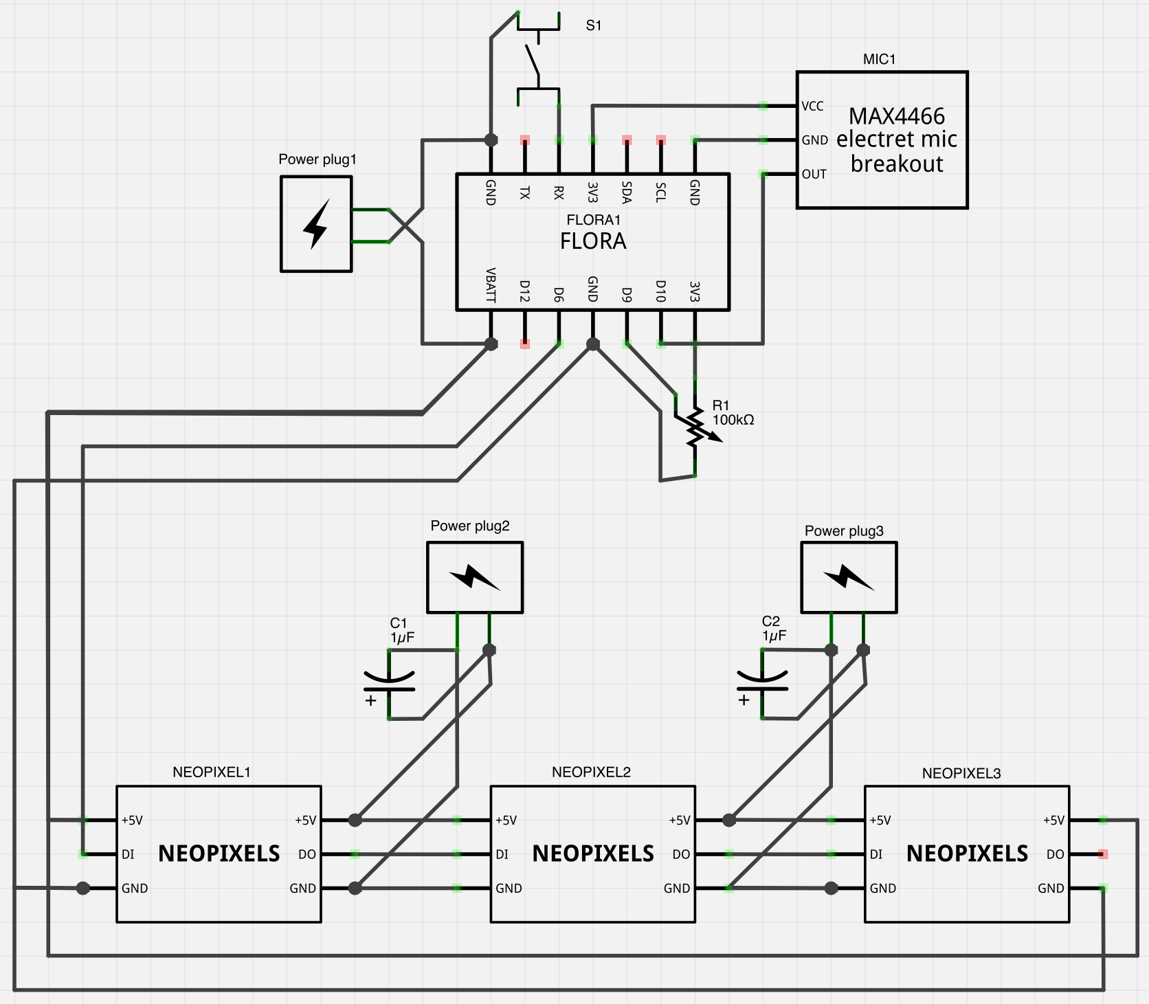
Room lights schematic" class="mt-image-none" height="1461
I’ve little idea what other people are doing for wiring things to Arduino boards, but my solution has been to solder male headers to the FLORA so I can easily swap components and use the commonly available jumper wires to test things. And obviously serve as the final product, since I haven’t felt compelled to package this more professionally since it’s for me!

My bedroom lights are currently powered by an Adafruit FLORA board, to which I soldered a bunch of header pins to make plug and play easier. Perhaps I ought to switch it out for a normal Arduino…
To attach the strips to the wall, I used some push pins. At first I tried a slightly more professional looking rubber holder, but then I realized I was putting twice as many holes in the wall as was really necessary.
 strips with some extra power and a capacitor.")
Joining two NeoPixels (WS2812) strips with some extra power and a capacitor.
Also note the Adafruit guide recommends placing a resistor between the board and the strip, but I omitted this.
I use a potentiometer to set the pixel brightness upon mode change. Alternatively, you may wish to periodically read the pot within the program instead of on mode change.
Program
See my last post for more background on the program I’m using.
I removed a bunch of color controlling functions I need to refine, but got the basic sound reactivity and rainbow modes into a new project that I checked into my Arduino Examples repository. This specific lighting project is in the
ceilingdirectory. I’m planning many improvements, but there it is.
The push button switch isn’t functioning that well right now. I may have to reevaluate how I am using interrupts to change the mode. Hopefully I’ve resolved this by the time anyone finds this post and uses the code. :-)
The push button switch I initially used worked unpredictably, and I resolved this by 1) adding a delay before resetting a variable used to track whether the button was pushed and 2) using a different button because apparently the one I used is meant as a on/off and nut just a momentary button. The change is reflected in the code.

Makeshift push button. Usually I solder the buttons directly to the Arduino, but I'm trying to make everything modular, and I knew how these buttons performed, so I went with it.
Product
As it stands, here’s a video of the sound reactive mode.
Sometimes I just put it in a simple rainbow mode for some lovely lighting.

I attached the monitor to the wall so there would be more room on my desk.

When reclining with my legs on the desk isn't relaxing enough, I switch to the projector and lie down in bed while maintaining productivity.